
Introduction
Supervisory Control and Data Acquisition (SCADA) serves as the backbone for digitalizing water management systems, playing a crucial role in achieving the goals set forth by Smart Dhaka WASA and Vision 2041. Smart WASA represents the integration of advanced digital technologies into the operations of the Water Supply and Sewerage disposal. This digital transformation aims to enhance operational efficiency, reduce commercial loss, optimize resource management, and improve services like providing pure drinkable water, reducing non-revenue water (NRW) through the seamless integration of SCADA with the water network.
SCADA is a comprehensive control system that enables real-time monitoring, data acquisition, and automated control of deep tube wells, treatment plants, transmission and distribution networks. Vision 2041 sets the overarching goals for a smart Bangladesh, where smart water supply management is a must, and this cannot be achieved without the integration of SCADA. As we navigate towards Vision 2041, the amalgamation of SCADA and Digital WASA promises to create a pathway towards a digitally empowered, environmentally sustainable, and socially inclusive future for Dhaka to meet the growing demands of a rapidly increasing population. Digitalization of DWASA will thus help to achieve its goal to be the best water utility in the public sector of Asia.
SCADA Components
Supervisory control and data acquisition (SCADA) is a system of software and hardware elements that allows industrial organizations to:
- Control DTW production processes locally or from remote locations.
- Directly interact with devices such as level sensors, pumps, motors, and more directly through Human Machine interface (HMI) software, monitor, gather, and process real- time data, record events into a log file.
- Monitor and control the water quality through the chlorine disinfection system.
- Monitor water quality through the online analyzer installed in different nodes of the distribution network.
- Water flow can be measured, monitored and controlled through e-prv system in transmission network.
SCADA Function
A SCADA system has the following functions:
- Data acquisition.
- Network data communication.
- data presentation.
- Monitoring and control.
- Trend
- Alarm and Event
- Report and archiving.
SCADA Communication topology
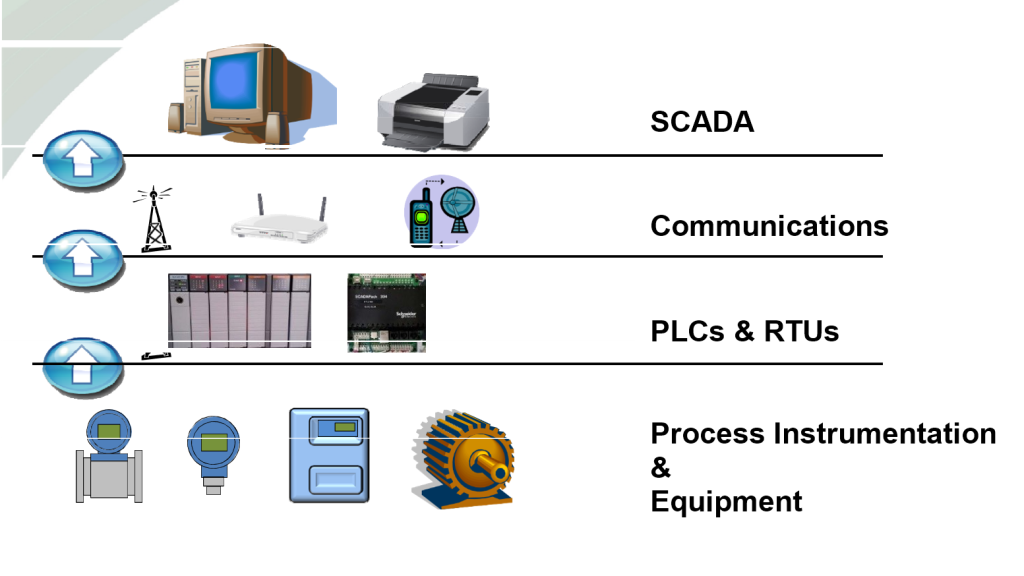
Hardware of SCADA
The hardware of SCADA is given below:
I. RTU (Remote Terminal Unit)/ PLC (Programmable logic Controller)
II. HMI (Human Machine Interface)/ MMI (Man Machine Interface)
III. Communication Network Equipment
IV. UPS
V. Field device & process Instruments
VI. SCADA Server Computers / Operational computer
Software of SCADA
Programming Software
The software used for SCADA system are listed below:
- SCADA Software SCADA Server (Geo SCADA Expert)
- PLC Programming software.
- Touch HMI configuration software
Program Back-up
It should be more emphasized that the final version of database and/or program, which have been developed for and related to SCADA system, should be backed up and stored in a safe place in order to restore the system in the event of system failure. Such backup includes:
- SCADA Software Database (located in SCADA Server)
- PLC program (located in PLC CPU)
- Touch HMI configuration (located in HMI or HMI configuration software)
- Ethernet Router configuration (the router located in SCADA room)
User Name and Password
Some of the hardware and/or software requires User Name/Password to access to and use the system. The following login information shall be kept in secure way.
- ID/Password for SCADA Server Computers
- ID/Password to login SCADA Software
- ID/Password for Ethernet Router located in SCADA room
- ID/Password for PLC programming software, if any.
- ID/Password for Touch HMI configuration software, if any.
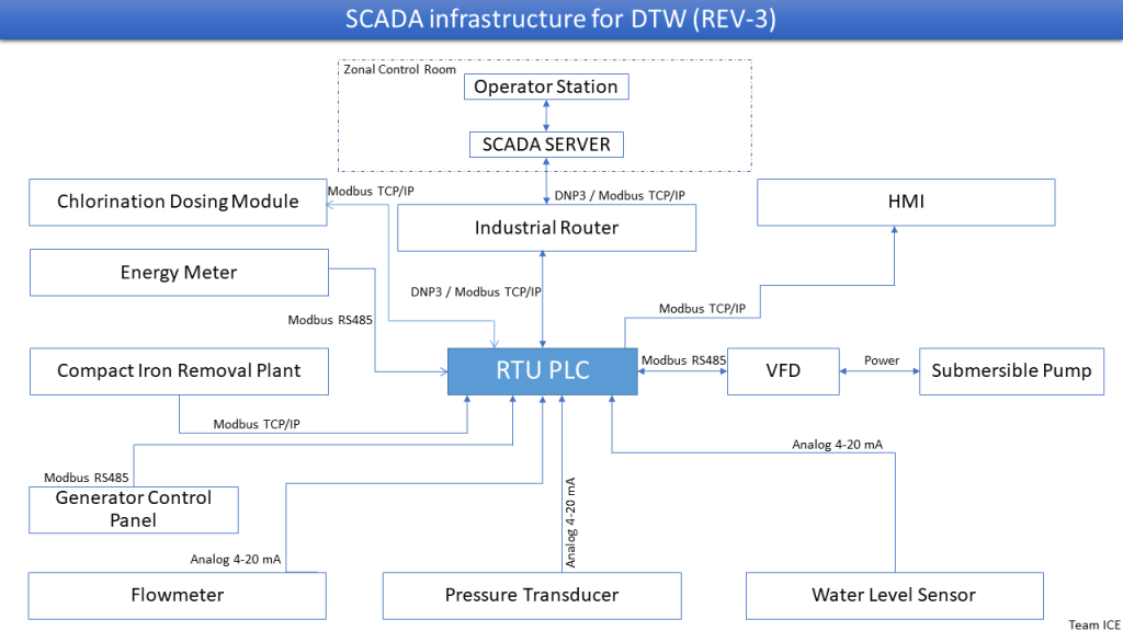
SCADA infrastructure
Automated Reporting
Automated reporting refers to the process in which data from remote process equipment is communicated to a central processing station by way of radio, Ethernet, etc. The data can then be automatically formulated into a report.
Operation Philosophy
The DTW SCADA is intended to operate the pump remotely located and geographically dispersed.
The operation of the DTW pump can be achieved in two (2) operation mode, local mode and SCADA mode (remote mode). The mode is selected by the selector switch located on the RTU panel. When the selector switch is placed to “Local”, the operation of the pump is conducted at the DTW compound by pressing start/stop buttons installed on RTU panel. When the selector switch is placed to “Remote”, the operation of the pump is performed by SCADA.
Local Mode Operation
- Selector switch on RTU panel shall be positioned to “Local”.
- The pump run/stop shall be conducted by pressing the “Start/Stop” buttons placed on the RTU panel.
- The position of selector switch is displayed on SCADA, but remote operation (start/stop command) at SCADA is disabled.
- All SCADA Functions (monitoring, alarm, trend and others, except the command functions) are available including the pump status, VFD status, instrument values, energy meter values, UPS status and others as long as SCADA/PLC /Communication are okay.
- This mode can be used in case SCADA is in troubled condition or during maintenance.
- However, the PLC should normally function in order to operate the pump in local mode, but SCADA is not used in local mode.
Remote Mode Operation (SCADA Operation)
- Selector switch on RTU panel shall be positioned to “Remote”.
- The pump run/stop shall be conducted by operating it from SCADA.
- All field signals, including pump/VFD status, instrument values, energy meter, UPS status are monitored on SCADA display, alarms are generated, and trend is available.
- Local operation of the pump is disabled in this case.
- If the selector switch on RTU panel is changed from “Remote” to “Local”, the pump will stop if the pump was running.
- Operator should check the communication status on SCADA display when giving start/stop commands. Only when the communication is indicated as “normal”, the commands will take effect.
Alarms
When abnormal operating conditions are identified by SCADA, the alarm is generated and displayed in the SCADA display for operator’s attention. Operator should acknowledge the alarm and take necessary action to clear it. Some alarms are forcing the pump to stop for safety and/or for avoidance of possible damage to the equipment, whilst most alarms are generated for the purpose of alerting abnormal situation to operator.
| Alarm | Cause of alarm |
| VFD Fault | VFD fault occurs due to overload, high temperature or any other protections. |
| CL Booster pump fault | Chlorine booster pump fault occurs. The pump is in fault due to overload or any other causes. |
| Chlorine Gas Detector Alarm | Gas leak from cylinder or pipeline. Gas detection sensor faulty. |
| Chlorine cylinder empty | Chlorine cylinder is empty. The sensor is faulty. |
| UPS battery low | UPS battery is low. |
| UPS Fault | UPS is in fault condition or turned off. |
| Water level low | Deep tube well water level is lower than the setpoint of SCADA -> pump will be forced to stop for safety. |
| Pressure high | Pump discharge is higher than the setpoint set in SCADA -> pump will be forced to stop for safety. |
| Communication Error | No communication between SCADA and GSM router for more than 10 seconds |
| Voltage Imbalance | 3 phase voltage difference > 20V |
| Current Imbalance | 3 phase current difference > 15A |
| Security alarms | Any trespassing in pump compound |
Parameter Setting
Some parameters are allowed to be changed by operator, by adjusting setpoint from SCADA or on the equipment at site, as the case may be, in accordance with operating condition.
| Parameter | Description | Setting Location | Set Range |
| VFD Frequency | Motor speed | SCADA | 0 – 50 Hz |
| Water Level Low | Water level low alarm setpoint | SCADA | 0 – 90m (depending on the rating of sensor) |
| Pressure High | Pump discharge pressure alarm setpoint | SCADA | 0 – 10 bar |
| Chlorine Dosing Rate | Chlorine Dosing Rate | SCADA | 0 – 30 ppd (depending on the rating of dosing system) |
Data Monitoring and Handling
Monitoring Data on SCADA
The following data shall be monitored real-time by SCADA.
- Pump Status (Remote/Local, Run/Stop/Fault)
- Chorine Booster Pump (Remote/Local, Run/Stop/Fault)
- Deep tube well Level
- Pump discharge Pressure
- VFD status (Frequency, Motor Ampere, Fault)
- Electric Data from Energy Meter (3 Phase Voltage/Current, Active Power, Reactive Power, Power Factor, Total Harmonic Distortion, Energy consumption)
- Chorine System Status (Booter pump, Injection ratio, Cylinder empty)
- Alarms (refer to section 5 (Alarm).
- Communication Status between SCADA and PLC(RTU)
- Water quality
Data Handling
User can handle various data by utilizing SCADA.
- Daily and monthly production report
- Power consumption report
- Daily and total pump run hour
- Alarm List
- Event List
- Trend Analysis (water level, flowrate & flow total, pressure, VFD data, Chlorine injection data, electrical data)
Daily Operational activities
| SL No | Main Task | Sub Task | Responsible Person |
| 1 | Control & Monitoring VFD | Turn On/Off remotely. | SCADA Operation Engineer |
| Turn On/Off locally if required. | Electrician | ||
| Adjust VFD Frequency. | FM Division | ||
| VFD Fault Monitoring. | SCADA Operation Engineer | ||
| Reporting of VFD frequency adjustment to FM division | FM Division | ||
| 2 | Water Production Monitoring | Real-time Water Production Monitoring (flowrate and flow total) | SCADA Operation Engineer |
| Periodic Water Production Logging | SCADA Operation Engineer | ||
| Total Water Production Log. | SCADA Operation Engineer | ||
| 3 | Line Pressure Monitoring | Real-time Line Pressure Monitoring | SCADA Operation Engineer |
| Periodic Line Pressure Logging | SCADA Operation Engineer | ||
| 4 | Underground Water Level Monitoring | Real-time water level monitoring | SCADA Operation Engineer |
| Periodic water level logging | SCADA Operation Engineer | ||
| 5 | Energy Monitoring | Line voltage | SCADA Operation Engineer |
| Line current | SCADA Operation Engineer | ||
| Power factor | SCADA Operation Engineer | ||
| Active power/energy | SCADA Operation Engineer | ||
| Real-time monitoring of energy parameters | SCADA Operation Engineer | ||
| 6 | RTU panel wiring check, IP address configuration etc. (if require) | SCADA Operation Engineer/ Electrician |
Maintenance and troubleshooting
Effective & Efficient operation are reflected through SCADA System troubleshooting & maintenance. Maintenance includes hardware and software updates, periodic testing, configuration changes, system optimization, and troubleshooting. SCADA system maintenance is critical for ensuring optimal performance, minimizing downtime, and minimizing potential security threats. A well-planned and executed maintenance program can help SCADA systems last longer, improve system reliability and safety, and lower overall operating costs.
Periodical Maintenance Service
In order to prevent unexpected failures of the equipment and system, a good planning is required to be established in order to organize act of performing regularly scheduled maintenance activities. Such preventive maintenance activities include the items tabulated below:
Weekly Maintenance
| Equipment / Device | Activity / Checkpoint | Description |
| RTU Panel | Cleaning | Using vacuum cleaner, clean the inside and outside of panel for any dust or foreign substances |
| Incoming Power | Using multi-meter, measure the input voltage to RTU panel to confirm the volage is within acceptable range. | |
| VFD Panel | Cleaning | Using vacuum, clean inside and outside of VFD panel |
| Any alarm | Check for any alarm message for any critical or non-critical alarm. If alarm exists, clear the alarm by taking required action coordination with FM division. | |
| Flowmeter | Accuracy of measurement | Measure the flowrate by reading the mechanical gauge of flow meter and compare it with SCADA reading. If not correct, check for PLC program or replace the flowmeter. |
| UPS | Any alarm | Check for any alarm on UPS, critical or non-critical, and clear any alarm, if exists, by taking necessary action. |
| Normal UPS function | Check if UPS is in normal operation mode or bypass mode. If in bypass mode, then find the cause and rectify it either by resetting it or replacing it. | |
| Energy Meter | Reading | Check the energy meter whether the reading values are within reasonable range. |
Monthly Maintenance
| Equipment / Device | Activity / Checkpoint | Description |
| General | All weekly activities | All weekly activities, as described in section 10.2, shall be carried out. |
| RTU Panel | Sealing | Check for any damage to sealing of cable entry to prevent any insects or animal from entering the panel. Seal it again using urethane form at any improper sealing place. |
| PLC Indication | Check for any alarm indication in the PLC. | |
| Loose connection | Check for the connection terminals for any loose cable connection. If found, tighten it. | |
| VFD Panel | Loose connection | Check for any loose connection of cable, including power and control cable connection, and tighten it if any loose connection. |
| Sealing | Check for any damage to sealing of cable entry to prevent any insects or animal from entering the panel. Seal it again using urethane form at any improper sealing place. | |
| Flowmeter Level sensor Pressure sensor | Loose connection | Check for any loose connection of cable at the point of sensor cable connection, including the connection inside junction box. |
| Junction box | Check the junction box for any ingress of water. Remove water and make it dry if any water exists. | |
| UPS | Function Test | Turn off the UPS input power and see if the UPS is supplying power to RTU panel and instruments. If not functioning properly, repair or replace the UPS. |
| Test for bypass mode | Change UPS to bypass mode by creating fault condition and check for proper transition to bypass mode. | |
| SCADA | Monthly Data | Check if the monthly data of SCADA are correct. Total pump run hour Monthly flow sum Monthly energy consumption If not, request a support from SCADA specialist. |
| Database backup | Backup the database of SCADA from SCADA server including historical data. |
Biannual Maintenance
| Equipment / Device | Activity / Checkpoint | Description |
| General | All weekly and monthly activities | All weekly and monthly maintenance activities shall be carried out, as described in section 10.2 and 10.3. |
| Pressure sensor / Pressure gauge | Calibration | Using hand pump and multi-meter (4-20mA readable multi-meter), calibrate the pressure sensor and pressure gauge by applying the pressure from zero to span. |
| Level Sensor | Calibration | Calibrate the level sensor, using hand pump and multi-meter (4-20mA readable multi-meter) by removing the level sensor, connecting it to hand pump, and then applying to level sensor the pressure, corresponding to the range of level (10.2 meter = 1 bar). |
| UPS | Battery backup time test | Check how long time the battery can last in accordance with the following procedure: Turn off UPS input breaker Start the timer Record the time of battery low alarm Record the time when UPS output is down. Turn back on UPS input breaker Compare the recorded time with the previous test result. if required, replace the battery. |
| SCADA / PLC/ Touch HMI / Ethernet Router | Full back up of program and configuration | Make full backup of the program and configuration. SCADA database and historical data PLC program Touch HMI configuration Ethernet router configuration |
Fault detection and troubleshooting
| Fault | Cause | Required Action |
| VFD Fault | – VFD fault occurs | Check the fault message on VFD display. Check for any loose cable connection. Remove the cause of fault and restart pump |
| Pump Start Fail | – Pump start failed | If the pump running feedback is not received by PLC within 5 seconds after the pump start command is given through SCADA, then “pump start fail” alarm shows up on SCADA display. Check on SCADA display if the communication with GSM router is normal. Check if all breakers are turned on. Check if the communication between PLC and VFD is working normally. |
| Pump Stop Fail | – Pump stop failed | If the pump running feedback is being received for 5 seconds after pump stop command is given by SCADA, “pump stop fail” alarm shows up on SCADA display. Check on SCADA display if the communication with GSM router is normal. Turn off the pump locally, and check PLC program to find the cause of such stop failure. |
| CL Booster pump fault | – Chlorin booster pump Overload | Check the Overload Relay. Reset the relay and start the pump and measure the current value using clamp meter. |
| Chlorine Gas Detector Alarm | – Gas leak – Gas detection sensor faulty | Check for any leakage of gas from cylinder or pipeline Rectify the leaked point. Replace the sensor if sensor is faulty. |
| Chlorine cylinder empty | Chlorine cylinder empty sensor activated | Check the proper function of empty sensor. Fill the cylinder with gas |
| UPS fault | UPS is in faulty condition | Charge the UPS battery by supplying proper power. If the battery goes low in short time (less than 30 min.) even after full charge, then replace the battery. |
| UPS Fault | UPS is in fault condition or turned off | Check the fault message of UPS and take necessary action in accordance with the fault condition. Replace the UPS if the fault is fatal. |
| Water level low | Deep tube well water level is lower than setpoint in SCADA -> pump is forced to stop for safety | Check if the level sensor is okay. If not, replace the level sensor. Change the setpoint to lower value in SCADA, if required. If level is okay (i.e., the sensor is faulty), then turn on “level interlock bypass” from SCADA during maintenance, which will allow the pump to be operated from SCADA by bypassing the level interlock. |
| Pressure high | Pump discharge is higher than setpoint of SCADA -> pump is forced to stop for safety | Check if pressure sensor is okay. If not, replace the pressure sensor. Check any blockage in the pipeline. |
| Communication Error | No communication between SCADA and GSM router for 10 seconds | Charge the data in the SIM of GSM router. Check if GSM router is working well. Check Ethernet router (located in SCADA room), in the event that most of communications are gone. |
| Voltage Imbalance | 3 phase voltage difference > 20V | Check the Energy meter at site to confirm actual voltage difference. If the alarm continues for more than 10 min. then stop the pump until the alarm is cleared by itself (grid voltage problem). |
| Current Imbalance | 3 phase current difference > 15A | Check the Energy meter at site to confirm actual voltage difference. Check the VFD current at site to confirm the actual current difference. If the current difference continues for more than 10 min., then check the pump motor (winding resistance) |
Cybersecurity
SCADA networks house critical systems – including computers and applications – that control, facilitate or handle essential data and information. That’s why, protection of SCADA from cyber-attacks is essential. Thus, SCADA cybersecurity can be optimized by taking the following ten (10) measures:
- Role-Based Access Control (RBAC):
- Establishing different user roles based on job responsibilities and grant permissions
accordingly. - Regular review and update of access permissions to ensure they align with current job roles and responsibilities.
- Implementing least privilege principles, giving users only the access necessary for their tasks.
2. Encryption:
– Using robust encryption algorithms for data to protect against unauthorized access.
– Implementing security protocols in communication channels between SCADA components, such as between sensors, controllers, and the central server.
– Employing end-to-end encryption to ensure data integrity and confidentiality.
3. Regular Updates and Patch Management:
– Developing a proactive patch management strategy to promptly apply security patches and updates.
– Regularly assessing and prioritizing vulnerabilities based on potential exploitability.
– Testing patches in a controlled environment before applying them to production systems to avoid unintended consequences.
4. Network Segmentation:
– Dividing the SCADA network into isolated zones to contain potential security breaches and limit lateral movement.
– Implementing firewalls and routers to control traffic between different segments.
– Clearly defining and enforcing communication rules between zones based on operational needs and security policies.
5. Firewalls:
– Deploying state-of-the-art firewalls to inspect and filter network traffic.
– Configuring firewalls to block unauthorized access attempts and to monitor and log all network activity.
– Regularly reviewing firewall configurations to adapt to evolving security threats.
6. Intrusion Detection Systems (IDS) and Intrusion Prevention Systems (IPS):
– Using IDS to monitor network or system activities for suspicious patterns and anomalies.
– Employing IPS to automatically respond to and prevent detected threats in real-time.
– Regular update of intrusion signatures and rules to enhance detection capabilities.
7. Authentication and Authorization:
– Implementing strong authentication mechanisms, such as multi-factor authentication, to ensure only authorized personnel access the SCADA system.
– Regular review and audit of user accounts and access logs to detect and address any unauthorized access attempts.
8. Physical Security Measures:
– Securing physical access to SCADA components, including servers, routers, and control panels.
– Implementing biometric access controls, surveillance through ip camera and restricted entry to critical infrastructure locations.
– Regular conduct of physical security audits to identify and address vulnerabilities.
9. Incident Response Plan:
– Developing a comprehensive incident response plan outlining procedures for detecting, responding to, and recovering from security incidents.
– Regular testing and updating the incident response plan to ensure its effectiveness and alignment with emerging threats.
– Establishing communication protocols and collaboration with relevant authorities in the event of a serious security incident.
10. Employee Training:
– Conducting regular cybersecurity awareness training sessions for all personnel involved in SCADA operations.
– Educating employees on recognizing phishing attempts, social engineering tactics, and other common cybersecurity threats.
– Fostering a culture of security awareness and encourage reporting of any suspicious activities.
By implementing and consistently maintaining these elaborate security protocols, SCADA system can significantly enhance its resilience against cyber threats. It’s crucial to approach SCADA security comprehensively, considering both technical and human factors to create a robust defense against potential risks.
